One rigid body on a building corner, seven coded targets, and a single shared frame for the drone, the ground station and the lidar — anchored to a datum that already exists in the BIM model.
An RTK drone gives absolute position with a bias of a few centimetres. A ground 360 capture gives excellent density and drifting scale. A mobile lidar gives a beautiful cloud in an internal SLAM frame nobody measured. All three describe the same building — and none of them agrees with the others.
The usual answer is to stitch afterwards: ICP between clouds, manual point picking, coarse alignment then refinement. It works, sometimes. The problem is not accuracy — it is that the result cannot be repeated and cannot be documented. There is no number to show the client, no residual to inspect, and if someone rescans in six months nothing ties the two surveys together.
This method inverts the order. Instead of matching clouds after the fact, you place one rigid body whose geometry is known in advance, and every sensor that sees it is tied to it — and through it, to each other.
Seven panels on one frame: three per arm — one lying on the slab, one at 45°, one flat against the facade — plus a seventh that anchors the corner itself. Targets sit flush in the print plane; no hardware stands proud of them.
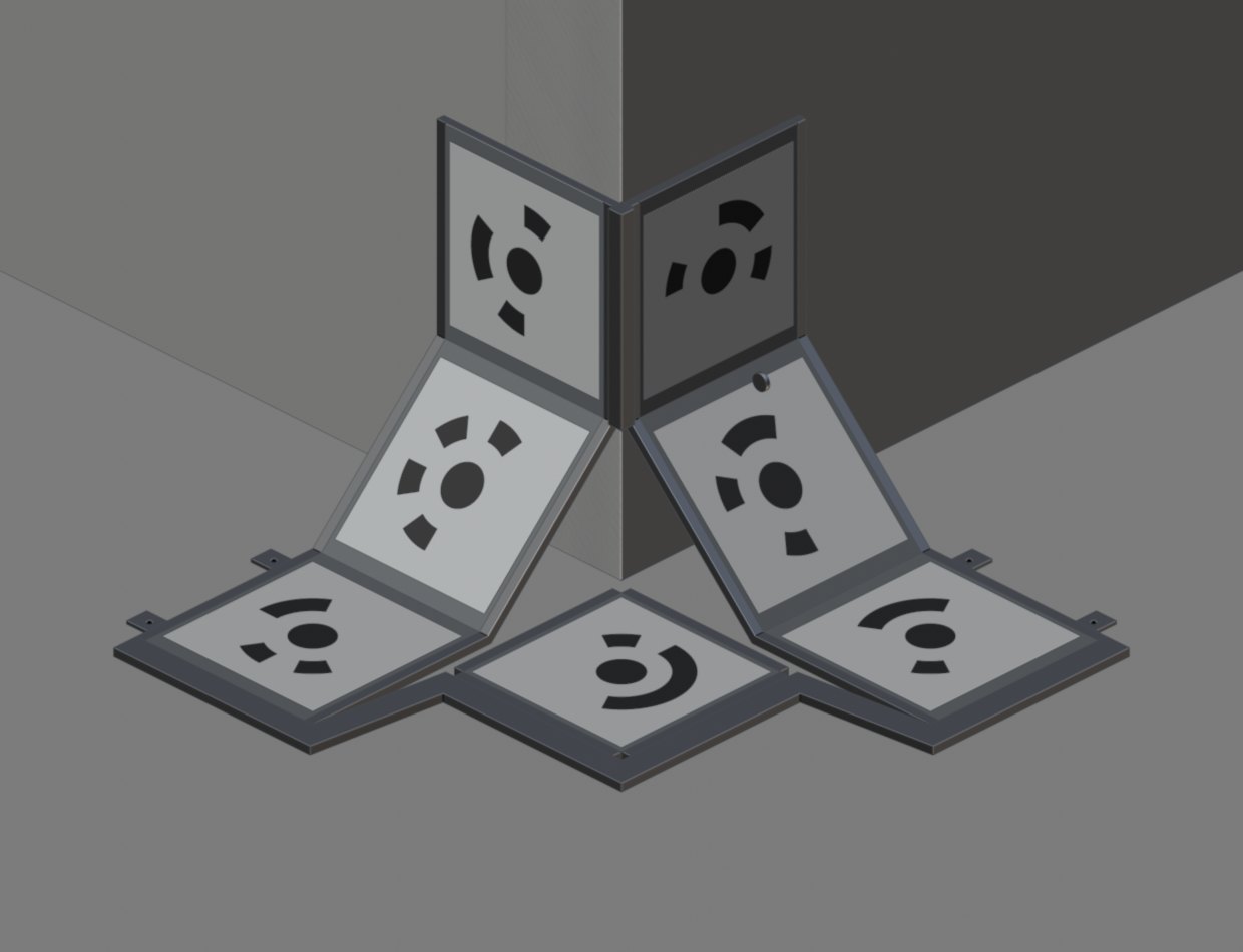
Every panel is cut from the same 550 × 610 mm blank, out of a standard 1220 × 2440 ACM sheet — eight blanks per sheet, zero waste. The frame is aluminium, 14.5 m in total. The fixture breaks down into two arms and a corner panel and fits a car boot at roughly 650 × 650 × 295 mm.
There is no round number in this fixture that was picked because it looked right. Each dimension falls out of a constraint — the raw sheet, Metashape's detection threshold, or the requirement that the fixture never obscures itself.
| Dimension | Value | The constraint that fixes it |
|---|---|---|
| Panel pitch | 610 | 1220 × 2440 ACM sheet — eight blanks, zero waste |
| Print face height | 31 | 6 mm pad stand-off + 25 mm frame depth |
| Stand-off from each facade | 31 | Equal to the height — symmetry, not convenience |
| Reach, and also height | 1072.3 | 31 + 610 + 610/√2 — equal by construction |
| Corner panel centre | 355 | 610/2 + 45 mm post + 5 mm clearance |
| Vertex to building corner | 70.7 | (355 − 305) × √2 — the closest possible |
| White media | 520 | 550 less a 15 mm margin each side |
| Ring diameter | 371.4 | 520 ÷ 1.4 — a 20% quiet zone |
| Inner dot diameter | 123.8 | Ring ÷ 3 — Metashape's 1:2:3 proportion |
The right-hand column is the point. Change the raw sheet and 610 moves with it; change the detection threshold and the print artwork changes. No dimension here is independent, which means no dimension can drift quietly.
This is the heart of the method. An external building corner is not a point somebody marked — it is a point the world has already defined, where three real lines meet.
Three lines, one point. It needs no paint, no peg and no marking — it is implied by three surfaces the builder already poured. And more importantly: that exact point exists as a vertex in the IFC model. Anchor to it and the survey and the model speak the same language without a separate control network.
The fixture locates on the corner by 3-2-1 kinematic constraint: three contacts on the slab, two on facade A, one on facade B. Six contacts for six degrees of freedom — no more, no fewer. No legs, no levelling, no shims. Set it on the corner and it is located. The CAD origin (0, 0, 0) is the building corner itself.
| Marker | Panel | X | Y | Z | From datum |
|---|---|---|---|---|---|
| target 1 | Slab A | −305.000 | 767.335 | 31.000 | 0.8263 m |
| target 2 | 45° A | −305.000 | 246.668 | 246.668 | 0.4634 m |
| target 3 | Facade A | −305.000 | 31.000 | 767.335 | 0.8263 m |
| target 4 | Slab B | 767.335 | −305.000 | 31.000 | 0.8263 m |
| target 5 | 45° B | 246.668 | −305.000 | 246.668 | 0.4634 m |
| target 6 | Facade B | 31.000 | −305.000 | 767.335 | 0.8263 m |
| target 7 | Corner anchor | 355.000 | 355.000 | 31.000 | 0.5030 m |
This geometry is checked on every build of the model: nothing sits in front of any print face, no part penetrates the facades or the slab, no two parts interfere, and mirror symmetry about the plane X = Y is proven part by part. Five checks, at boolean-volume level — not assumptions.
Seven markers produce 21 independent distances, from 0.4752 m to 1.5165 m — a 3.19× spread of scales, every one of them known in CAD.
The difference between one scale bar and 21 is the difference between belief and measurement. With a single bar, a bad observation quietly rescales the model. With 21 independent distances the system is over-determined: an outlier shows up as a residual instead of as a scale error. That residual is something you can put in front of a client.
Three points are enough to fix a rigid six-degree-of-freedom transform. Seven give more than double the redundancy — and therefore robustness: if one marker is obscured, dirty, or falls outside the frame, the solution is still fixed and still checked.
Occupy the building corner once with RTK. The moment that point is known in world coordinates, all seven markers are known with it — because their offsets from it are fixed in CAD to the micron. And everything registered to those markers — drone, ground capture, lidar — comes along into the same frame.
The export is a CSV in metres at micron precision, with a 1 mm accuracy field per axis. It loads straight into Metashape as Reference.
Detect Markers with CircularTarget12bit finds the targets and decodes their IDs. The CSV is imported and binds by label. No manual point picking, at any stage.
For that to actually work, the printed rings have to be legal codes. That is less obvious than it sounds: of the 4096 possible 12-bit ring patterns, only 266 decode at all, and they collapse to exactly 161 IDs — 1 through 161. An illegal pattern prints perfectly and is never detected, with no warning of any kind.
161 IDs ÷ 7 markers = 23 fixtures on one site before the 12-bit space runs out. There is no need to move to 14- or 16-bit.
The detector also has a size window: the inner dot radius has to land roughly between 5 and 40 pixels. Too large fails exactly as reliably as too small — worth knowing if you photograph a big target from very close.
These targets were sized around a 15 pixel threshold on the inner dot. With a 123.8 mm dot and a Mavic 3E wide lens, that gives automatic detection out to 31 m.
The question that matters is not "can you see the fixture" but where can you see at least three markers. Three is the minimum for a rigid transform. The maps below are an actual count: a marker scores only if it is inside the frame, facing the camera, larger than 15 pixels after foreshortening, and unoccluded.
| Elevation | −80 | −70 | −60 | −50 | −40 | −30 | −20 | −10 | 0 | 10 | 20 | 30 | 40 | 50 | 60 | 70 | 80 |
|---|---|---|---|---|---|---|---|---|---|---|---|---|---|---|---|---|---|
| 80° | 4 | 4 | 5 | 5 | 5 | 5 | 5 | 5 | 5 | 5 | 5 | 5 | 5 | 5 | 5 | 4 | 4 |
| 70° | 4 | 4 | 4 | 4 | 5 | 5 | 5 | 5 | 5 | 5 | 5 | 5 | 5 | 4 | 4 | 4 | 4 |
| 60° | 4 | 4 | 4 | 4 | 4 | 5 | 5 | 5 | 5 | 5 | 5 | 5 | 4 | 4 | 4 | 4 | 4 |
| 50° | 4 | 4 | 5 | 5 | 5 | 4 | 5 | 5 | 5 | 5 | 5 | 4 | 5 | 5 | 5 | 4 | 4 |
| 40° | 3 | 3 | 3 | 3 | 3 | 3 | 4 | 2 | 2 | 2 | 4 | 3 | 3 | 3 | 3 | 3 | 3 |
| 30° | 2 | 2 | 2 | 2 | 2 | 2 | 2 | 3 | 2 | 3 | 2 | 2 | 2 | 2 | 2 | 2 | 2 |
| 20° | 2 | 2 | 2 | 2 | 2 | 2 | 2 | 2 | 2 | 2 | 2 | 2 | 2 | 2 | 2 | 2 | 2 |
| 10° | 2 | 2 | 2 | 2 | 2 | 2 | 2 | 2 | 2 | 2 | 2 | 2 | 2 | 2 | 2 | 2 | 2 |
The operational conclusion for the drone: at 20 m the envelope is open from 40° elevation upward, at any azimuth — 3 to 5 markers. Below 30° coverage drops to two. A flight plan that holds 40° or above gets the whole fixture.
| Distance | −80 | −60 | −40 | −20 | 0 | 20 | 40 | 60 | 80 | Elevation |
|---|---|---|---|---|---|---|---|---|---|---|
| 2 m | 5 | 6 | 7 | 7 | 7 | 7 | 7 | 6 | 5 | 36° |
| 3 m | 5 | 5 | 7 | 7 | 7 | 7 | 7 | 5 | 5 | 26° |
| 4 m | 5 | 5 | 6 | 7 | 7 | 7 | 6 | 5 | 5 | 20° |
| 5 m | 5 | 5 | 6 | 7 | 7 | 7 | 6 | 5 | 5 | 16° |
| 6 m | 4 | 4 | 4 | 7 | 7 | 7 | 4 | 4 | 4 | 14° |
| 8 m | 2 | 2 | 2 | 4 | 4 | 4 | 2 | 2 | 2 | 10° |
| 10 m | 2 | 2 | 2 | 4 | 4 | 4 | 2 | 2 | 2 | 8° |
| 14 m | 2 | 2 | 2 | 2 | 4 | 2 | 2 | 2 | 2 | 6° |
And that overlap is what the method is built around. The drone looks down and sees mostly the slab panels and the corner panel. The ground scanner, at a metre and a half, sees mostly the facade panels. The 45° panels are visible to both — they are the bridge. Five distinct surface normals on one rigid body is what lets two sensors at opposing angles share identified targets.
This trips a lot of people up, so it is worth saying plainly. In pure geometry a printed target is invisible: it is flush in the panel plane, with no bump and no recess. But lidar does not only measure XYZ — it measures return intensity.
At 905 nm, carbon-black ink returns about ρ ≈ 0.06 and matte white vinyl about ρ ≈ 0.80. A ratio near 13:1. The rings stand out in the intensity channel exactly as they do in a photograph.
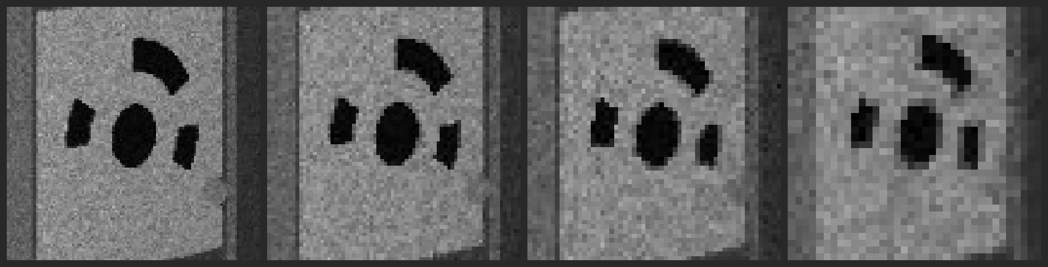
The mechanism exists and works: importing a structured scan with is_laser_scan generates a panorama camera from the scan, and Detect Markers runs on it exactly as on a photograph. The panorama is built at a resolution matched to the scan density.
The table below is an actual run of Metashape's own detector over synthetic scans of the fixture, carrying the seven legal codes:
| Station | Point spacing | Angular | Inner dot | Detected |
|---|---|---|---|---|
| Ground, 2 m | 2.5 mm | 1.26 mrad | 25–33 px | 7 / 7 |
| Ground, 2 m | 4.0 mm | 2.05 mrad | 16–20 px | 7 / 7 |
| Ground, 2 m | 6.0 mm | 3.07 mrad | 10–14 px | 7 / 7 |
| Ground, 4 m | 3.0 mm | 0.77 mrad | 15–25 px | 7 / 7 |
| Ground, 4 m | 5.0 mm | 1.29 mrad | 9–15 px | 7 / 7 |
| Ground, 4 m | 6.0 mm | 1.58 mrad | 7–12 px | 7 / 7 |
| Ground, 4 m | 8.0 mm | 2.05 mrad | 5.5–9 px | 4 / 7 |
| Ground, 4 m | 12.0 mm | 3.07 mrad | 3.7–6 px | 1 / 7 |
| Airborne, 30 m | 8.0 mm | 0.27 mrad | 8–13 px | 6 / 7 |
| Airborne, 30 m | 12.0 mm | 0.41 mrad | 5–9 px | 4 / 7 |
| Airborne, 30 m | 20.0 mm | 0.66 mrad | 3–5 px | 0 / 7 |
| Airborne, 30 m | 30.0 mm | 1.02 mrad | 2–3 px | 0 / 7 |
Rule of thumb: you need about 7 points across the inner dot, measured along the surface. For a 123.8 mm dot that means an on-surface spacing of 17 mm or less.
Note "along the surface". Foreshortening counts in full. A target lying on the slab is struck at 68.6° from a tripod at 1.5 m and 4 m out, so its effective spacing is 2.7× the nominal figure. That is why standing at 2 m beats 4 m — not because of range but because of angle: it brings incidence down to 45–53° and restores 7 out of 7 even on a relatively coarse scanner.
Do not chase ring decoding from the air. The fixture is already an excellent geometric lidar target: seven planes in five distinct normal directions, with relative pose exact to the millimetre in CAD. Even at 20 mm airborne spacing each 550 mm panel still collects about 750 points — ample for fitting planes to the CAD model and recovering all six degrees of freedom. Airborne registration then rides on the same rigid frame the photogrammetric markers sit on.
A coded-target detector works on local contrast, not absolute brightness. A target in full sun and a target in full shade are both decoded. What breaks decoding is a hard shadow edge crossing the ring and splitting it into two brightness regimes.
So that is exactly what was measured: 384 sun directions over the hemisphere (azimuth 0–345° in 15° steps, elevation 10–85° in 5° steps), sampling each target at 81 points over the area the detector actually reads — the inner dot and the coded ring.
| Marker | Uniformly lit | Uniformly shaded | Split | Of which: by the rig | Sun behind |
|---|---|---|---|---|---|
| Slab A | 255 | 86 | 43 | 26 | 0 |
| 45° A | 196 | 74 | 56 | 49 | 58 |
| Facade A | 173 | 0 | 3 | 3 | 208 |
| Slab B | 257 | 86 | 41 | 24 | 0 |
| 45° B | 212 | 74 | 40 | 33 | 58 |
| Facade B | 176 | 0 | 0 | 0 | 208 |
| Corner anchor | 251 | 71 | 62 | 53 | 0 |
Splitting caused by the fixture's own hardware amounts to 188 of 2688 marker-direction combinations, or 7.0%. And here is the whole picture, counted per sun direction:
The requirement is 3. The measurement says at least 4 at every hour of the day, from every direction. There is no window in which it is a bad time to go out.
The two facade panels barely split at all (3 and 0 out of 384) — they are the most shadow-immune, and they are also the ones the ground scanner sees best. That is not luck: a panel flat against a wall with no hardware in front of it has almost nothing that can cast an edge onto it.
The six kinematic contacts seat themselves — three on the slab, two on one facade, one on the other. No levelling, no adjustment.
One measurement of the building corner. From there all seven markers are known in world coordinates.
Drone at 40° elevation or above; ground station between 2 and 6 m; laser scanner at 2 m if you want automatic detection in the cloud as well.
CircularTarget12bit. IDs decode themselves and become labels.
Load the CSV. Binding is by label — not a single point picked by hand.
The 21 distances leave the system over-determined. Those residuals are the evidence you can show a client.
Every claim here was measured. These are the things that were measured and came back negative, and they belong in the picture as much as the rest.
| Item | Specification | Quantity |
|---|---|---|
| ACM sheet | 1220 × 2440 × 4 mm, 8 blanks per sheet | 1 sheet |
| Worked area | Seven identical 550 × 610 blanks | 2.32 m² |
| Aluminium profile | Panel frames, beams, corner post | 14.5 m |
| Total mass | Assembled fixture | 12 kg |
| Transport volume | Two arms and corner panel, folded | 650 × 650 × 295 mm |
Zero waste on the sheet, one part repeated seven times, and it goes through an ordinary house door. Building four fixtures for the four corners of a structure consumes 28 of the 161 available IDs — still nowhere near the ceiling.
About the numbers. Every figure in this document was measured, not estimated. The geometry is built procedurally and checked on every build by five boolean-volume tests. The coverage maps are a virtual-camera count using the Mavic 3E lens model, including ray-cast occlusion. The lidar results are a run of Metashape 2.3.2's own detector over synthetic structured scans with a physical return model, speckle noise and range noise. The shadow sweep is 384 sun directions over the decoded area only. The table of legal codes was recovered by brute force — all 4096 patterns through the detector — and round-tripped, 161 of 161, zero wrong IDs.
The Viewer does not perform the survey adjustment or invent accuracy. It brings measured outputs, source, position, time and residual evidence into one permission-aware project environment.
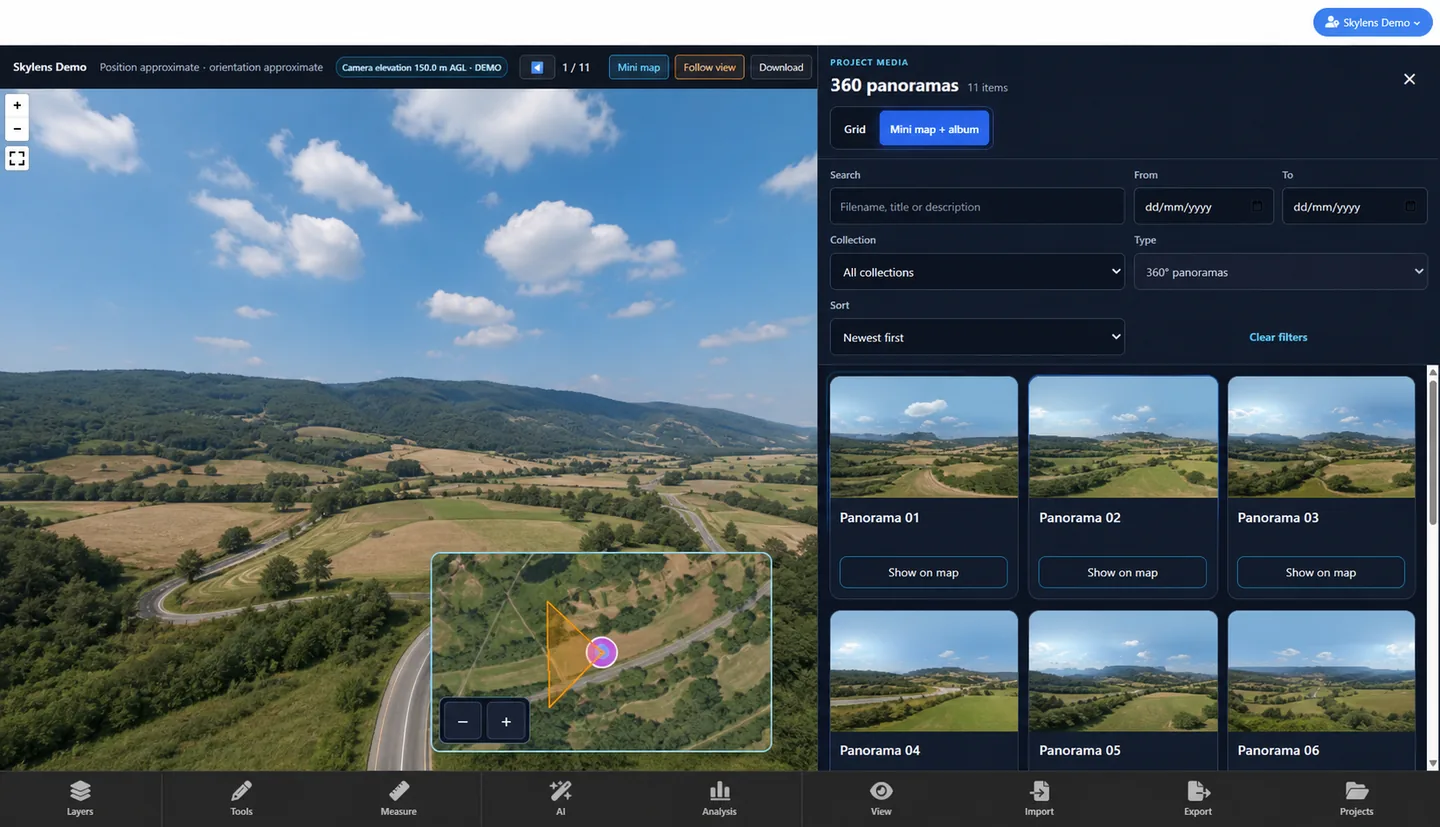 Project album, position and capture date — anonymized demo
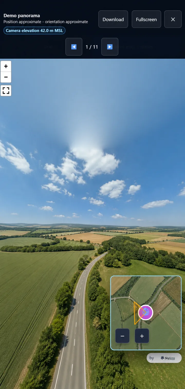 Panorama and mini map on mobile — anonymized demo
Complete one form and choose the data types you want to upload. If approved, you will receive a personal demo workspace for material you own or are authorized to use.
Demo access and uploaded material will remain available for up to 30 days from the date access is granted.
Page analytics records funnel progress only. It never includes passwords, survey files or the professional details you type.
